
Product description
for supporting girders, beams, binding joists, ceilings, etc.
Are used for heavy loads up to 15 N/mm2 (N 15) or up to 20 N/mm2 (N 20)
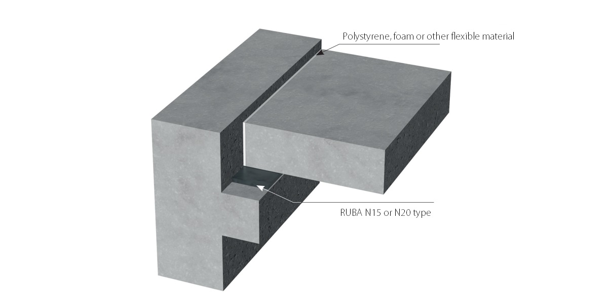
Unreinforced elastomeric washers ensure that the load is transferred to the support in a controlled manner, and they ensure free rotation on the support and reduce the impact related to the horizontal displacement of the supported element. They prevent excessive load eccentricities and stress concentrations at the edge of the support, while compensating for unevenness and deviations of adjacent surfaces.
1. Technical and assembly instructions.
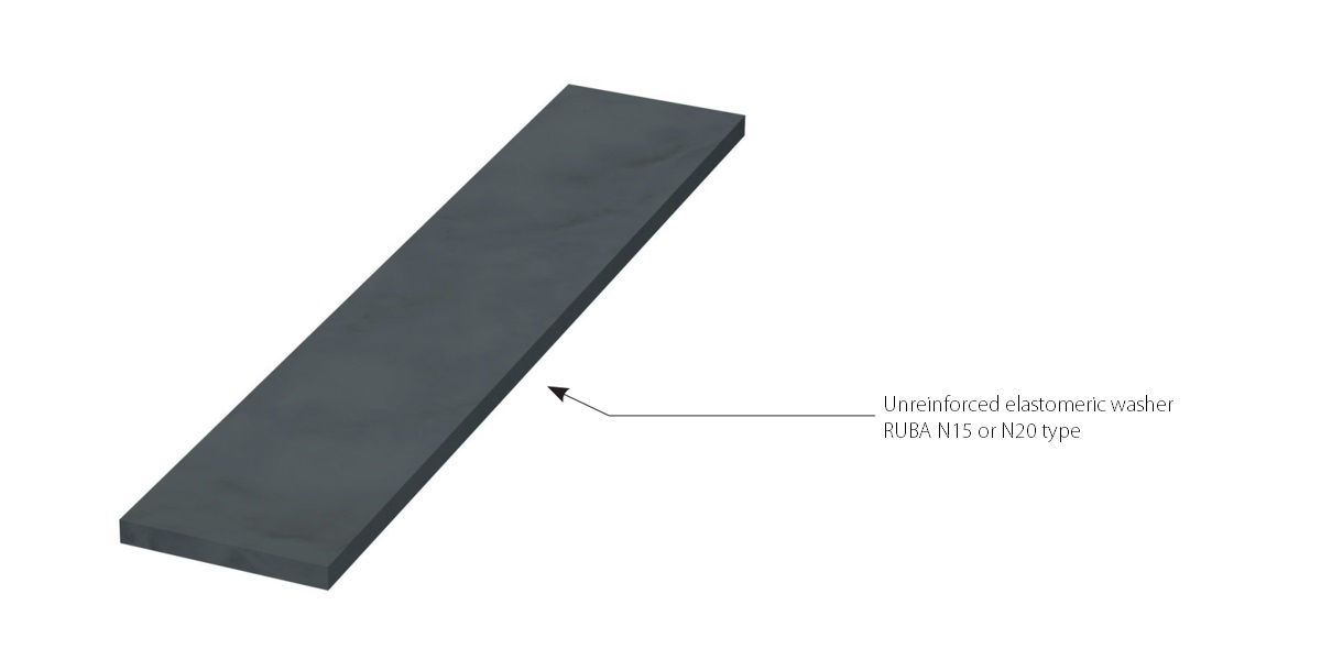
N 15 and N 20 unreinforced elastomeric washers are produced in thicknesses of 5 mm, 10 mm, 15 mm and 20 mm. The shorter side should be at least five times the thickness of the washer. The washer should be placed in the area of the static reinforcement of the support and the supported element.
2. Unreinforced elastomeric washers should be used mainly when static loads are present. For dynamic loads, reinforced elastomeric washers should be used.
Unreinforced elastomeric washers included in bearing class 2 can only be used if the long-term load share is 75% or more. In other cases where overloading or damaging the washer may lead to the loss of stability of the structure, we recommend using steel-reinforced elastomeric washers.
3. The load perpendicular to the spacer surface (surface load)
According to the currently binding inspection criteria of the Building Research Institute (Instytut Techniki Budowlanej), unreinforced elastomeric washers under certain load conditions may compress by 30% with respect to their initial thickness. In the following design tables, the maximum linear flattening has been limited to approximately 20% to provide additional safety in the event of possible assembly inaccuracies.
4. Design guidelines
According to the currently binding inspection criteria of the Building Research Institute (Instytut Techniki Budowlanej), unreinforced elastomeric washers under certain load conditions may compress by 30% with respect to their initial thickness. In the following design tables, the maximum linear flattening has been limited to approximately 20% to provide additional safety in the event of possible assembly inaccuracies.

The maximum allowable deformation angle and the displacement are calculated as follows:
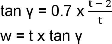
tan γ - the deformation angle [-],
t - the washer thickness [mm],
w - he characteristic displacement [mm].
Permanent loads parallel to the bearing plane are not allowed. For short-term loads, it is recommended to fulfil the condition of protection against the displacement:
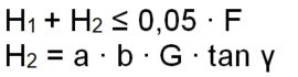
H1 = the characteristic external horizontal load [N],
H2 = the characteristic internal force resulting from the deformation [N],
tan γ = the deformation angle [-],
G = the shear modulus (1,5 N/mm²),
F = the characteristic surface load [N],
a,b = the length of washer sides [mm].
In the case of short-term external horizontal loads, the maximum permissible deformation angle should not be exceeded.
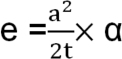
The permissible rotation angle resulting from elastic and plastic deformation of the supported element and partly from unevenness and bevel of the surface is calculated as follows:
![]()
α = the characteristic torsion angle
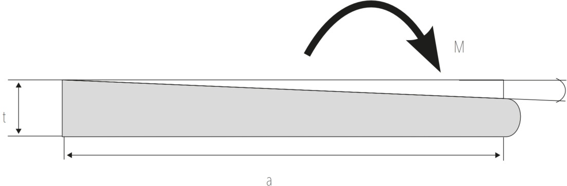
When dimensioning the structure elements, the possibility of the load eccentricity caused by the washer deformation should be taken into account.
e = the eccentricity
![]()
Transverse tensile forces due to linear deformation of the washer
Zq = the transverse tensile force [N]
F = the surface load [N]
t = the washer thickness [mm]
a = the shorter side of the washer [mm]
In order for the support to absorb the transverse tensile force, additional reinforcement must be made in the support element.
If at least two washers of different sizes are placed in one line under one component, the following proportion must not be exceeded:
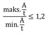 If at least two washers of different sizes are placed in one line under one component, the following proportion must not be exceeded:
Specification: t x b x l mm RUBA N 15 or N 20 type

5. Specification: t x b x l mm RUBA N 15 or N 20 type
the total thickness of 5 mm: the load in kN
| N15 | N20 | ||||||||||||||||||
| [mm] | 50 | 75 | 100 | 125 | 150 | 175 | 200 | 250 | 300 | [mm] | 50 | 75 | 100 | 125 | 150 | 175 | 200 | 250 | 300 |
| 50 | 38 | 56 | 75 | 94 | 113 | 131 | 150 | 188 | 225 | 50 | 47 | 75 | 100 | 125 | 150 | 175 | 200 | 250 | 300 |
| 75 | 56 | 84 | 113 | 141 | 169 | 197 | 225 | 281 | 338 | 75 | 75 | 113 | 150 | 188 | 225 | 263 | 300 | 375 | 450 |
| 100 | 75 | 113 | 150 | 188 | 225 | 263 | 300 | 375 | 450 | 100 | 100 | 150 | 200 | 250 | 300 | 350 | 400 | 500 | 600 |
| 125 | 94 | 141 | 188 | 234 | 281 | 328 | 375 | 469 | 563 | 125 | 125 | 188 | 250 | 313 | 375 | 438 | 500 | 625 | 750 |
| 150 | 113 | 169 | 225 | 281 | 338 | 394 | 450 | 563 | 675 | 150 | 150 | 225 | 300 | 375 | 450 | 525 | 600 | 750 | 900 |
| 175 | 131 | 197 | 263 | 328 | 394 | 459 | 525 | 656 | 788 | 175 | 175 | 263 | 350 | 438 | 525 | 613 | 700 | 875 | 1050 |
| 200 | 150 | 225 | 300 | 375 | 450 | 525 | 600 | 750 | 900 | 200 | 200 | 300 | 400 | 500 | 600 | 700 | 800 | 1000 | 1200 |
The shortest length of the side is 50 mm.
the total thickness of 10 mm: the load in kN
| N15 | N20 | ||||||||||||||||||
| [mm] | 50 | 75 | 100 | 125 | 150 | 175 | 200 | 250 | 300 | [mm] | 50 | 75 | 100 | 125 | 150 | 175 | 200 | 250 | 300 |
| 50 | 12 | 25 | 42 | 52 | 63 | 73 | 83 | 104 | 125 | 50 | 12 | 25 | 42 | 52 | 63 | 73 | 83 | 104 | 125 |
| 75 | 25 | 59 | 103 | 141 | 169 | 197 | 225 | 281 | 338 | 75 | 25 | 59 | 103 | 154 | 211 | 246 | 281 | 352 | 422 |
| 100 | 42 | 103 | 150 | 188 | 225 | 263 | 300 | 375 | 450 | 100 | 42 | 103 | 188 | 250 | 300 | 350 | 400 | 500 | 600 |
| 125 | 52 | 141 | 188 | 234 | 281 | 328 | 375 | 469 | 563 | 125 | 52 | 154 | 250 | 313 | 375 | 438 | 500 | 625 | 750 |
| 150 | 63 | 169 | 225 | 281 | 338 | 394 | 450 | 563 | 675 | 150 | 63 | 211 | 300 | 375 | 450 | 525 | 600 | 750 | 900 |
| 175 | 73 | 197 | 262 | 315 | 378 | 459 | 525 | 659 | 788 | 175 | 73 | 246 | 350 | 438 | 525 | 613 | 700 | 875 | 1050 |
| 200 | 83 | 225 | 300 | 375 | 450 | 525 | 600 | 750 | 900 | 200 | 83 | 281 | 400 | 500 | 600 | 700 | 800 | 1000 | 1200 |
The shortest length of the side is 50 mm.
the total thickness of 15 mm: the load in kN
| N15 | N20 | ||||||||||||||||||
| [mm] | 75 | 100 | 125 | 150 | 175 | 200 | 250 | 300 | 350 | [mm] | 75 | 100 | 125 | 150 | 175 | 200 | 250 | 300 | 350 |
| 75 | 26 | 46 | 69 | 94 | 109 | 125 | 156 | 188 | 219 | 75 | 26 | 46 | 69 | 94 | 109 | 125 | 156 | 188 | 219 |
| 100 | 46 | 83 | 129 | 180 | 236 | 269 | 370 | 444 | 519 | 100 | 46 | 83 | 129 | 180 | 236 | 296 | 370 | 444 | 519 |
| 125 | 69 | 129 | 203 | 281 | 328 | 375 | 469 | 563 | 656 | 125 | 69 | 129 | 203 | 291 | 388 | 493 | 625 | 750 | 875 |
| 150 | 94 | 180 | 281 | 338 | 394 | 450 | 563 | 675 | 788 | 150 | 94 | 180 | 291 | 422 | 525 | 600 | 750 | 900 | 1050 |
| 175 | 109 | 236 | 328 | 394 | 459 | 525 | 656 | 788 | 919 | 175 | 109 | 236 | 388 | 525 | 613 | 700 | 875 | 1050 | 1225 |
| 200 | 125 | 296 | 375 | 450 | 525 | 600 | 750 | 900 | 1050 | 200 | 125 | 269 | 493 | 600 | 700 | 800 | 1000 | 1200 | 1400 |
| 250 | 156 | 370 | 469 | 563 | 656 | 750 | 938 | 1125 | 1313 | 250 | 156 | 370 | 625 | 750 | 875 | 1000 | 1250 | 1500 | 1750 |
The shortest length of the side is 75 mm.
the total thickness of 20 mm: the load in kN
| N15 | N20 | ||||||||||||||||||
| [mm] | 100 | 125 | 150 | 175 | 200 | 250 | 300 | 350 | 400 | [mm] | 100 | 125 | 150 | 175 | 200 | 250 | 300 | 350 | 400 |
| 100 | 47 | 72 | 101 | 133 | 167 | 208 | 250 | 292 | 333 | 100 | 47 | 72 | 101 | 133 | 167 | 208 | 250 | 292 | 333 |
| 125 | 72 | 114 | 163 | 218 | 277 | 407 | 488 | 570 | 651 | 125 | 72 | 114 | 163 | 218 | 277 | 407 | 488 | 570 | 651 |
| 150 | 101 | 163 | 237 | 321 | 413 | 563 | 675 | 788 | 900 | 150 | 101 | 163 | 237 | 321 | 413 | 618 | 844 | 984 | 1125 |
| 175 | 133 | 218 | 321 | 440 | 525 | 656 | 788 | 919 | 1050 | 175 | 133 | 218 | 321 | 440 | 572 | 869 | 1050 | 1225 | 1400 |
| 200 | 167 | 277 | 413 | 525 | 600 | 750 | 900 | 1050 | 1200 | 200 | 167 | 277 | 413 | 572 | 750 | 1000 | <|||