Installation of balcony connectors when balconies are made on site
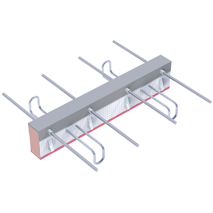
Thermotec F connectors can accommodate unidirectional bending moments and bidirectional shear forces. Shear forces in one direction are transferred by bearings as in A type connectors, forces in the other direction are transferred by hangers. Its main advantages are:
Shear capacities in the + direction given in tables have been prepared for typical cases and the reinforcement ratio at the level of 0.5% and 1%. Load capacities for higher ratios of the reinforcement, elements close to edges and connector systems can be determined according to the procedure in the last chapter of the catalogue. Thermotec F balcony connectors enable the transfer of transverse forces and bending moments acting in two directions.
Characteristics of the Thermotec B connector: :
Thermotec F designation scheme
For the correct operation of Thermotec F balcony connectors, the minimum ratio of the moment and the shear force specified in the table is required
| covering c =30 mm | ||||||||||
| h [mm] | 160 | 170 | 180 | 190 | 200 | 210 | 220 | 230 | 240 | 250 |
| emin [m] | 0,13 | 0,15 | 0,17 | 0,19 | 0,21 | 0,22 | 0,24 | 0,26 | 0,28 | 0,30 |
| covering c =35 mm | ||||||||||
| h [mm] | 165 | 170 | 180 | 190 | 200 | 210 | 220 | 230 | 240 | 250 |
| emin [m] | 0,13 | 0,14 | 0,16 | 0,18 | 0,20 | 0,21 | 0,23 | 0,25 | 0,26 | 0,29 |
| covering c =50 mm | ||||||||||
| 0h [mm] | - | - | 180 | 190 | 200 | 210 | 220 | 230 | 240 | 250 |
| emin [m] | - | - | 0,13 | 0,15 | 0,17 | 0,19 | 0,21 | 0,22 | 0,24 | 0,26 |
Thermotec F connector dimension
| Connector type | Number of sleeves | Number or bearings | Number of hengers | c | L | H | Lbd |
| mm | mm | mm | mm | ||||
| 4x14-1-1000 | 4 | 4 | 1 | 30-50 | 1000 | 160-250 | The anchore/overlap is alaways individually for Thermotec F1 connectors. |
| 4x14-2-1000 | 4 | 4 | 2 | 1000 | |||
| 6x14-3-1000 | 6 | 6 | 3 | 1000 | |||
| 2x14-1-500 | 2 | 2 | 1 | 500 | |||
| 4x14-2-500 | 4 | 4 | 2 | 500 | |||
| 4x14-3-500 | 4 | 4 | 3 | 500 | |||
| 2x14-1-250 | 2 | 2 | 1 | 250 |
Lambda equivalent table of Thermotec F connectors
| H | 160 | 170 | 180 | 190 | 200 | 210 | 220 | 230 | 240 | 250 | ||||||||||
| Type | λeq | Req | λeq | Req | λeq | Req | λeq | Req | λeq | Req | λeq | Req | λeq | Req | λeq | Req | λeq | Req | λeq | Req |
| 4x14-1000 | 0,32 | 0,25 | 0,31 | 0,26 | 0,29 | 0,27 | 0,28 | 0,29 | 0,26 | 0,30 | 0,25 | 0,32 | 0,24 | 0,33 | 0,23 | 0,34 | 0,22 | 0,36 | 0,22 | 0,37 |
| 5x14-1000 | 0,40 | 0,20 | 0,38 | 0,21 | 0,36 | 0,22 | 0,34 | 0,23 | 0,32 | 0,25 | 0,31 | 0,26 | 0,30 | 0,27 | 0,29 | 0,28 | 0,27 | 0,29 | 0,26 | 0,30 |
| 6x14-1000 | 0,48 | 0,17 | 0,45 | 0,18 | 0,43 | 0,19 | 0,40 | 0,20 | 0,39 | 0,21 | 0,37 | 0,22 | 0,35 | 0,23 | 0,34 | 0,24 | 0,32 | 0,25 | 0,31 | 0,26 |
| 7x14-1000 | 0,55 | 0,14 | 0,52 | 0,15 | 0,49 | 0,16 | 0,47 | 0,17 | 0,45 | 0,18 | 0,43 | 0,19 | 0,41 | 0,20 | 0,39 | 0,20 | 0,38 | 0,21 | 0,36 | 0,22 |
| 8x14-1000 | 0,63 | 0,13 | 0,59 | 0,13 | 0,56 | 0,14 | 0,53 | 0,15 | 0,51 | 0,16 | 0,48 | 0,17 | 0,46 | 0,17 | 0,44 | 0,18 | 0,43 | 0,19 | 0,41 | 0,20 |
| 2x14-500 | 0,32 | 0,25 | 0,31 | 0,26 | 0,29 | 0,27 | 0,28 | 0,29 | 0,26 | 0,30 | 0,25 | 0,32 | 0,24 | 0,33 | 0,23 | 0,34 | 0,22 | 0,36 | 0,22 | 0,37 |
| 3x14-500 | 0,48 | 0,17 | 0,45 | 0,18 | 0,43 | 0,19 | 0,40 | 0,20 | 0,39 | 0,21 | 0,37 | 0,22 | 0,35 | 0,23 | 0,34 | 0,24 | 0,32 | 0,25 | 0,31 | 0,26 |
| 4x14-500 | 0,63 | 0,13 | 0,59 | 0,13 | 0,56 | 0,14 | 0,53 | 0,15 | 0,51 | 0,16 | 0,48 | 0,17 | 0,46 | 0,17 | 0,44 | 0,18 | 0,43 | 0,19 | 0,41 | 0,20 |
| 2x14-250 | 0,63 | 0,13 | 0,59 | 0,13 | 0,56 | 0,14 | 0,53 | 0,15 | 0,51 | 0,16 | 0,48 | 0,17 | 0,46 | 0,17 | 0,44 | 0,18 | 0,43 | 0,19 | 0,41 | 0,20 |
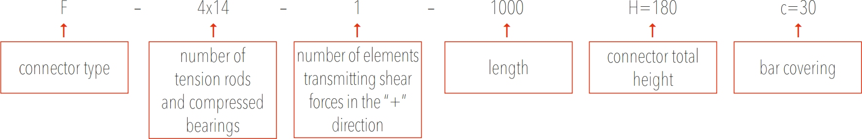
Assembly instructions - Thermotec F
1. Installation and levelling of formwork.
2. Installation and levelling of formwork.
3. Installation of Thermotec connector body.
4. Installation of screwed reinforcement (bars should be screwed in as far as it will go - min. 14 mm).
5. Binding the connector to the existing reinforcement.
6. Binding the connector to the existing reinforcement .
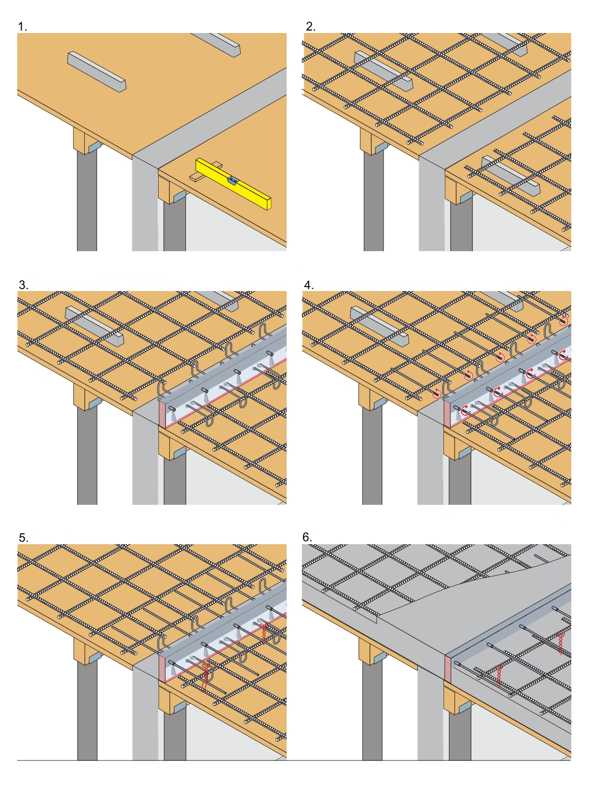
Installation of balcony connectors when balconies are made in prefabrication workshop
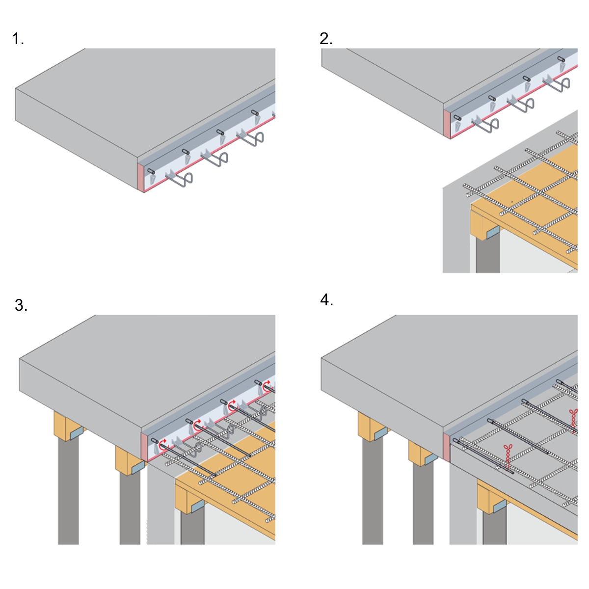
1. Preparation of the slab in the prefabrication workshop.
2. Installation of the prefabricated element at the destination place after it has been transported to the construction site.
3. Installation of screwed reinforcement (bars should be screwed in as far as it will go - min. 14mm , and linked to the slab reinforcement.
4. Pouring the slab .
Notes:
- strictly observe the assembly direction marked on the connector.
- the presented diagram is a recommendation that draws attention to the most important aspects of connector assembly.
Specific cases and solutions used on the construction site may need to be completed. The contractor is responsible for the correct installation method. In order to clarify any questions or doubts, please contact the EXTREA technical department.