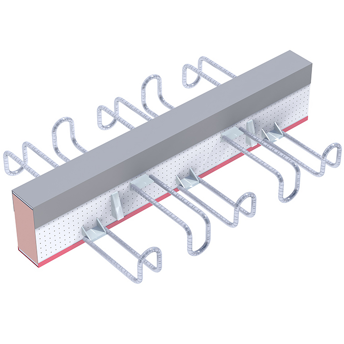
Thermotec D connector
Thermotec D connectors allow for a safe and easy to install method of connecting the ceiling with the supported balcony slab in places where bi-directional shear forces may occur. These connectors only transfer shear forces acting in two directions, not transfer bending moments.
Their main advantages are:
Load capacities given in tables have been prepared for typical cases and the reinforcement ratio at the level of 0.5% and 1%. Load capacities for higher ratios of the reinforcement, elements close to edges and connector systems can be determined according to the procedure in the last chapter of the catalogue Connectors allow transfer of transverse forces acting on the joint of the supported balcony slab and the ceiling slab in two directions.
Characteristics of the Thermotec D connector:
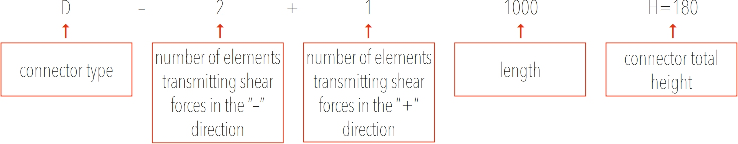
Thermotec D designation scheme
Connectors dimensions
| Thermotec D | ||||||
| Connector type | Number of hangers "-" | Number of hangers "+" | Number of bearings | io | L | H |
| mm | mm | mm | ||||
| 2+1-1000 | 2 | 1` | 2 | 30-120 | 1000 | 160-250 |
| 3+2-1000 | 3 | 2 | 2 | 1000 | ||
| 2+1-500 | 2 | 1 | 2 | 500 | ||
Lambda equivalent table of Thermotec D connectors
| H | 160 | 170 | 180 | 190 | 200 | 210 | 220 | 230 | 240 | 250 | ||||||||||
| Typ | λeq | Req | λeq | Req | λeq | Req | λeq | Req | λeq | Req | λeq | Req | λeq | Req | λeq | Req | λeq | Req | λeq | Req |
| 2+1-1000 | 0,20 | 0,41 | 0,19 | 0,43 | 0,18 | 0,45 | 0.17 | 0,48 | 0,16 | 0,50 | 0,15 | 0,52 | 0,15 | 0,54 | 0,14 | 0,56 | 0,14 | 0,58 | 0,13 | 0,60 |
| 3+2-1000 | 0,24 | 0,33 | 0,23 | 0,35 | 0,22 | 0,37 | 0,21 | 0,39 | 0,20 | 0,40 | 0,19 | 0,42 | 0,18 | 0,44 | 0,17 | 0,46 | 0,17 | 0,48 | 0,16 | 0,49 |
| 2+1-500 | 0,37 | 0,22 | 0,35 | 0,23 | 0,33 | 0,24 | 0,31 | 0,25 | 0,30 | 0,27 | 0,29 | 0,28 | 0,27 | 0,29 | 0,26 | 0,30 | 0,25 | 0,32 | 0,24 | 0,33 |
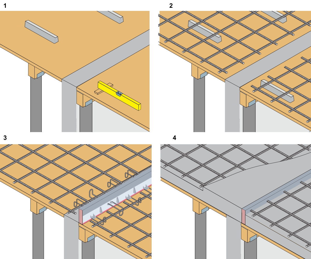
Assembly instructions - Thermotec D
Installation of balcony connectors when balconies are made on site:
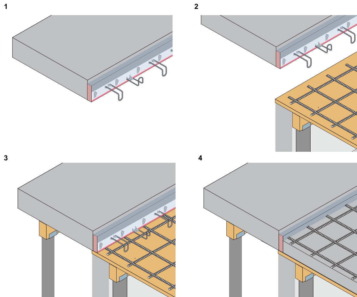
Installation of balcony connectors when balconies are made in prefabrication workshop
Notes:
- strictly observe the assembly direction marked on the connector.
- the presented diagram is a recommendation that draws attention to the most important aspects of connector assembly.
Specific cases and solutions used on the construction site may need to be completed. The contractor is responsible for the correct installation method. In order to clarify any questions or doubts, please contact the EXTREA technical department.